Visual Communication in Architectural Design
August 2, 2023
The most powerful tools employed by architects throughout the architectural design process are the methods of visual communication used to effectively illustrate and convey ideas, principles and concepts to a broad audience, including clients, contractors, and consultants. At the start of the architectural design process, the architect gathers critical information from the client to gain a better understanding of the desired architectural goals and objectives for their house.
When initiating a custom residential house design, the architect may inquire regarding the client’s family, pets, lifestyle, and living patterns to further inform the appropriate size and number of primary and secondary living spaces, bedrooms, and bathrooms. Questions and considerations related to the site, neighborhood context, nearby commercial buildings, desired architectural design style and aesthetics are among a long list of topics the architect may discuss with the client.
Additional information gathered by the architect often includes a mix of descriptive words, design inspiration images, context photos, site specifics, and zoning ordinance requirements. At the conclusion of the initial data collection exercise, it is the responsibility of the architect to synthesize the information and to formulate a thoughtful design solution that carefully considers all planning parameters for the house. The architect then prepares a conceptual design strategy and options that are generally expressed with a variety of visual and graphic art and design communication methods.
In the beginning of the design process, concepts and visual communications prepared by the architect are very basic. Over time and with input by the client and their family, the concepts are further refined and developed in increasing levels of detail as appropriate. At each stage of development in the design process, decisions regarding the architecture are made that provide the foundation on which additional details, materials and spatial relationships are elaborated upon in the space. It is a continuous process of the architect preparing sketches, drawings and model examples that advance the aspects of the initial schematic architecture concept, with the client reviewing and offering constructive feedback along the way.
As the project design evolves and coalesces, the architect prepares more detailed visual and graphic communications that further illustrate the design intent and relationship to the site, landscape, and natural topography.
Experienced architects are trained with numerous forms of tools, skills, and strategies to effectively communicate architectural design concepts to clients who may otherwise struggle to understand and interpret traditional two-dimensional drawings and graphics. Architects and designers with such skill can make houses and architecture feel like forms of art.
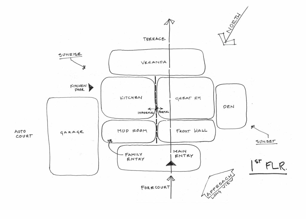
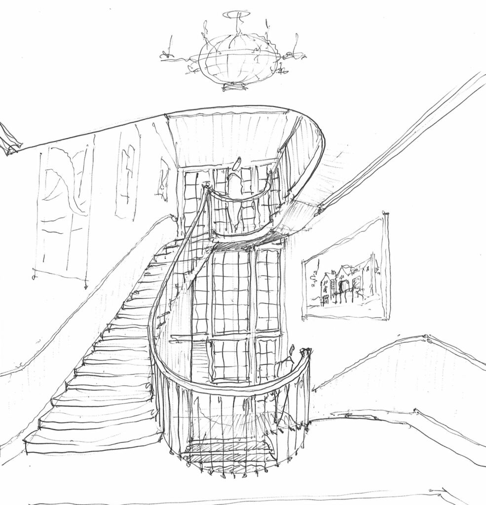
In the early design phases of a creation, architects often will visually communicate with hand sketches and simple line drawings as an efficient and effective means of transposing ideas. As planning, style and architectural concepts solidify, there is emphasis on the transition from hand-drawings and sketches to more detailed, computer-assisted 2-D and 3-D drawings, renderings, examples and models.
TWO-DIMENSIONAL TOOLS FOR ARCHITECTURAL VISUAL COMMUNICATION
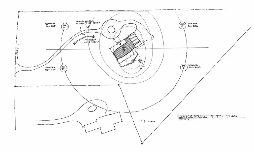
One of the primary two-dimensional drawings prepared at the beginning of projects is the CONCEPTUAL SITE PLAN. A site plan drawing illustrates an aerial top-down view of the physical boundaries of the property on which the structure, office or home is to be built. Additionally, the site plan illustrates important features such as adjoining structures, utilities, roads, driveways, mature trees, vegetation, topography, bodies of water, wetlands, and easements among other nature features that are considered by the architect when siting and designing structures.
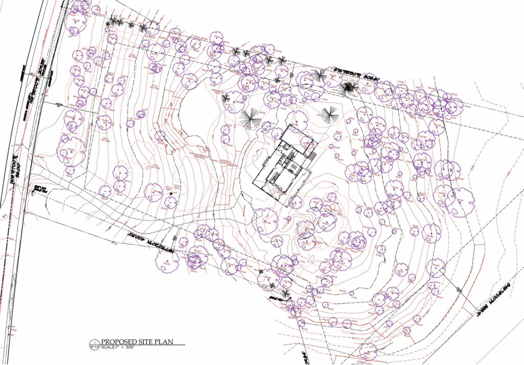
The architect evaluates a variety of factors such as solar orientation to maximize natural daylighting opportunities and minimize solar heat gain, orientation of primary view sheds, environmental sustainability, and existing topographical features to name a few examples. As the architectural design for the projects are further developed, the architect will create a computer-generated plan that is prepared with detailed and specific site information.
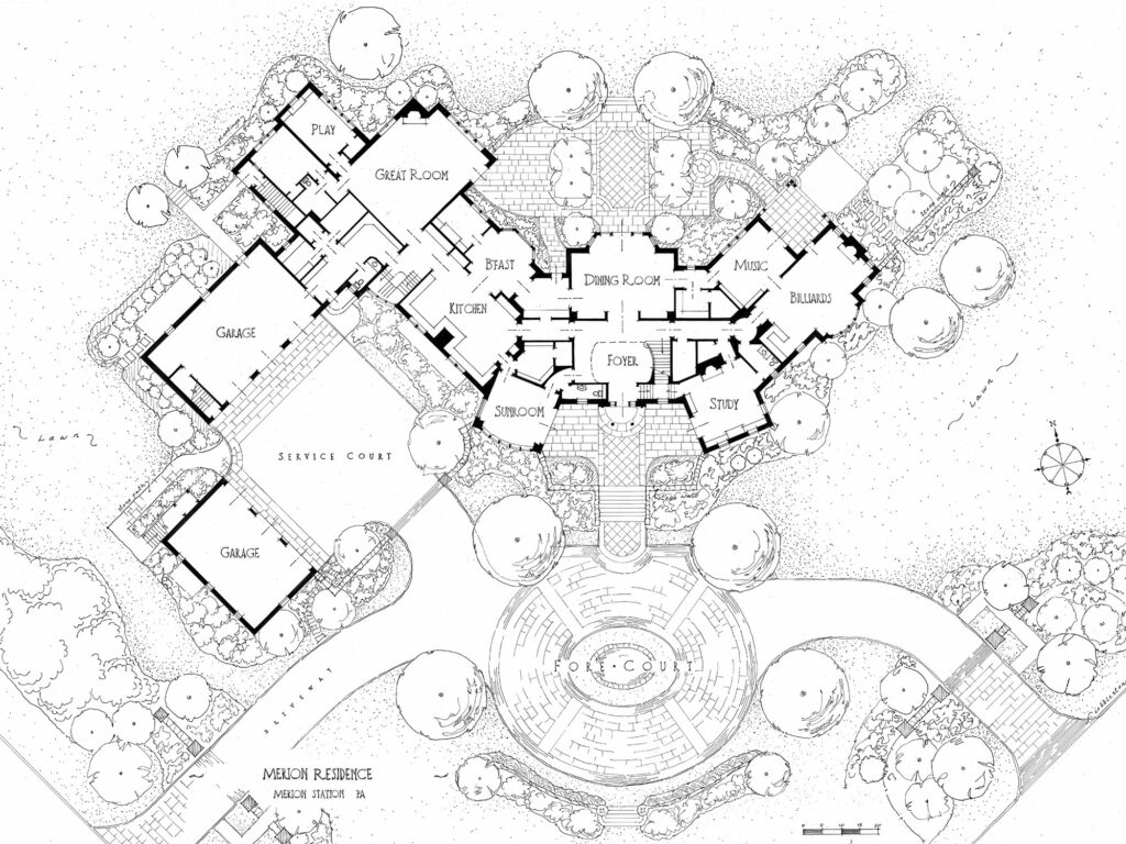
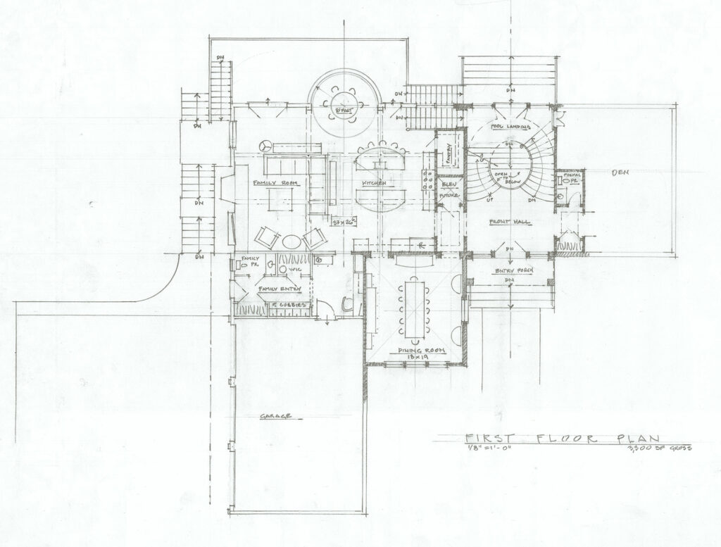
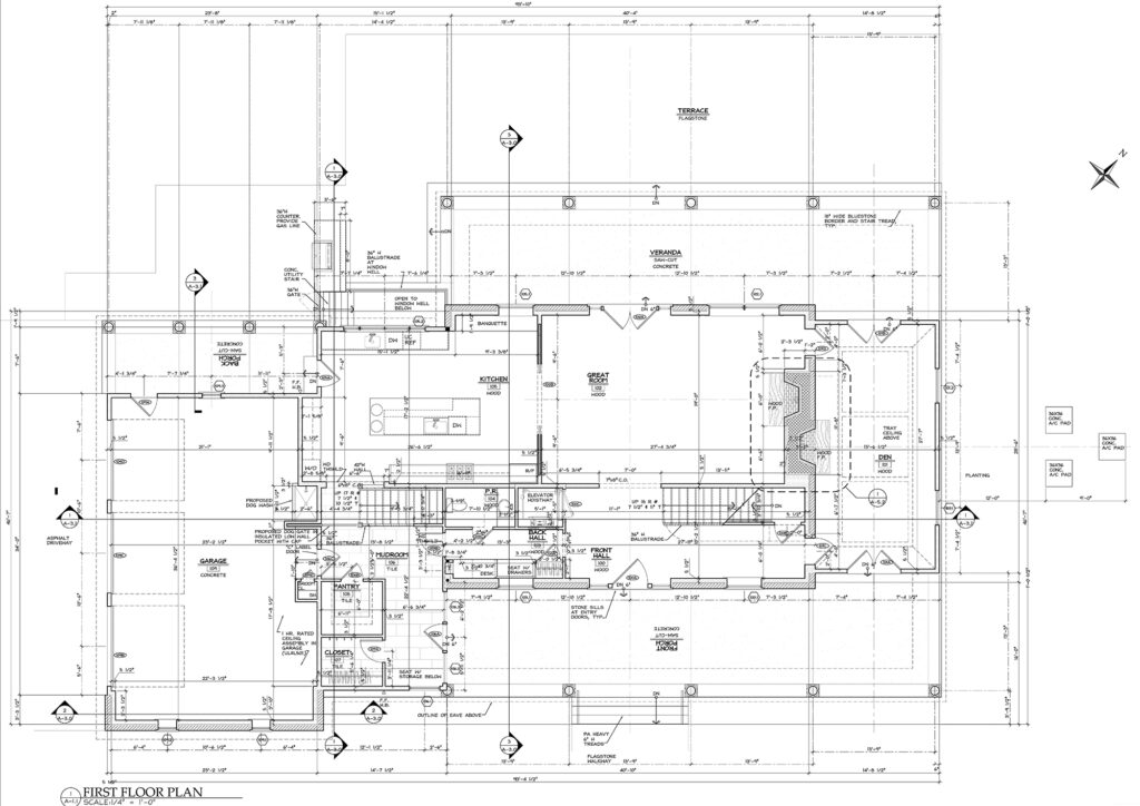
Perhaps the most recognized example of a specific two-dimensional drawing that architects are known to prepare is the ARCHITECTURAL FLOOR PLAN. With floor plan drawings, an architect will visually and graphically communicate the intended spatial configuration and adjacencies of each room on each floor of the building. The location of walls, doors, windows, and other architectural features are illustrated by architects in the FLOOR PLAN.
Often initiated as hand-drawings and sketches, the floor plans for each story of the building are advanced into computer-aided drafting programs as the architecture develops. Additional information, detailed measurements and notes depicting and specifying all the building elements and components are documented in the FLOOR PLAN.
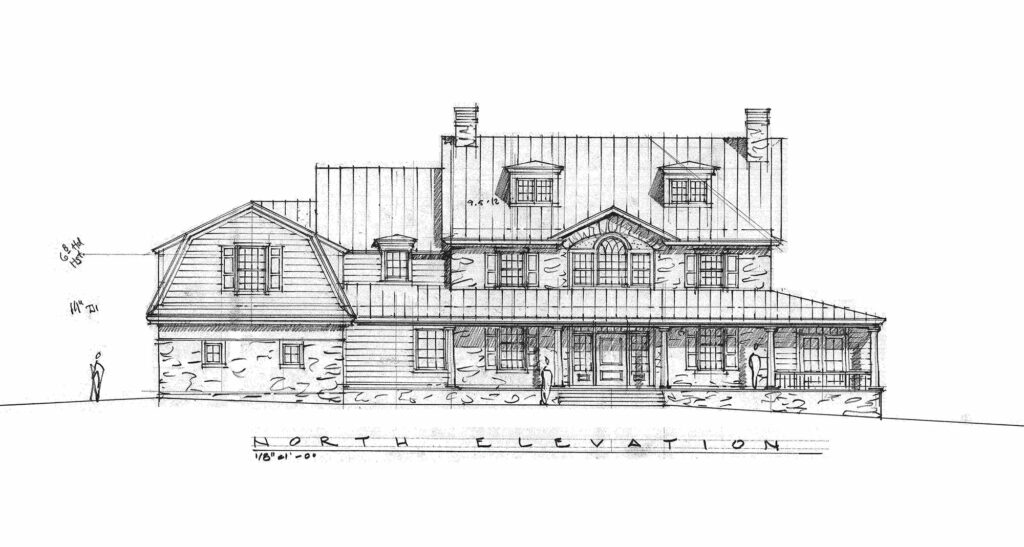
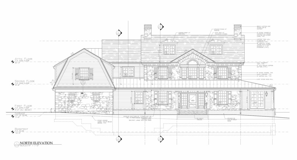
An incredibly important two-dimensional drawing prepared by the architect is the EXTERIOR ELEVATION. Exterior Elevation drawings are graphic illustrations representing each “side” of a building. 2-D exterior elevation drawings are orthogonal projections that show the outline; proportion and shape of buildings; door and window sizes and locations; and other exterior features, materials, and architectural embellishments of buildings such as covered porches, railings, chimneys, etc. As with the other early architectural concept sketches, EXTERIOR ELEVATION drawings are often hand-drafted before being input into a computer-aided drafting program where additional notes and measurements are added.
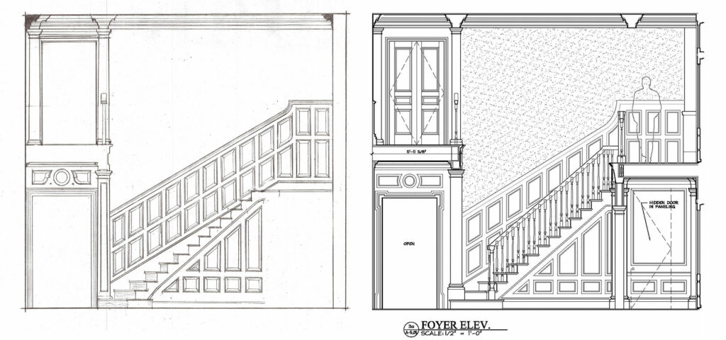
Similar to the EXTERIOR ELEVATION drawing is the INTERIOR ELEVATION. An interior elevation drawing illustrates the visual architectural intent and spatial relationships of doors and windows, built-in furniture and cabinetry, and detailed millwork such as paneling, moulding, and wood trim as experienced from the interior of the home.
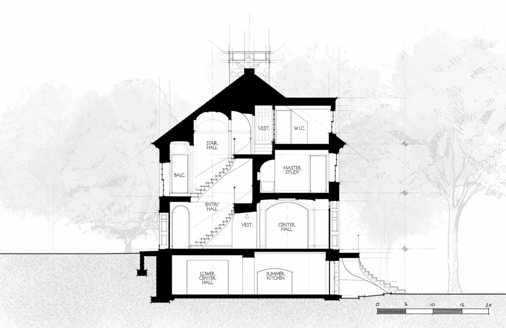
Perhaps the most misinterpreted and confusing drawing prepared by the architect is the BUILDING SECTION. A building section drawing represents a theoretical vertical slice through buildings from the utmost part of the roof structure all the way down to the lowest level of the building foundations. The Building Section drawing is prepared to better illustrate volumes, ceiling heights and spatial relationships of interior and exterior spaces and the structure’s relationship to the adjoining topography.
THREE-DIMENSIONAL ARCHITECTURAL VISUAL COMMUNICATION TOOLS FOR A DISTINCTIVE STRUCTURE
PERSPECTIVE DRAWINGS, SKETCHES & MODELS are tools often used by architects to represent complex three-dimensional architectural design concepts for buildings and spaces via a combination of drawing, rendering, and modeling techniques.
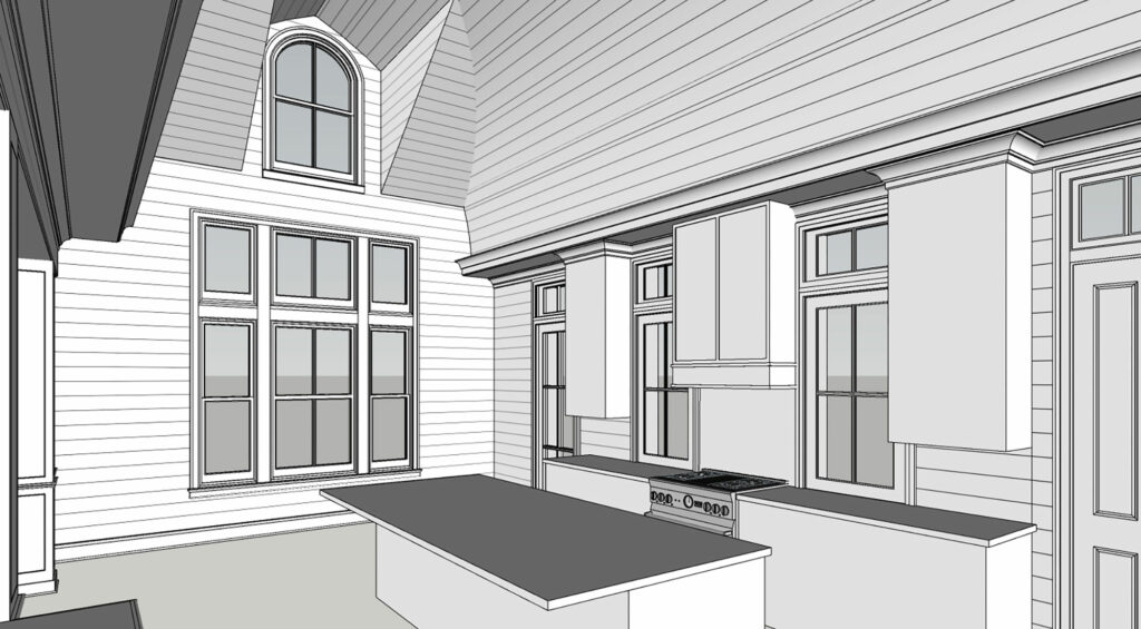
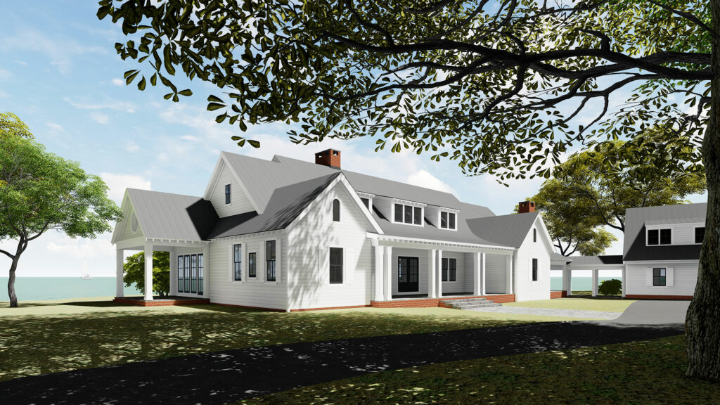
There are a variety of digital graphic tools and computer-aided drafting programs that allow architects to create practical, THREE-DIMENSIONAL VISUALIZATIONS ranging from creating a simple black and white perspectival line drawing to more advanced, photorealistic color renderings.
At Archer & Buchanan, we strive to incorporate three-dimensional architecture visualizations on almost all of our architecture projects. Computer-aided drafting software programs such as Revit and SketchUp are tools architects employ to generate three-dimensional graphic representations that allow the study and refinement of the architecture, building massing, volumes, systems, components, materials, details, site, architectural context and all other aspects of the architectural design as are appropriate.
Supplemental software programs such as Lumion and Photoshop are tools architects employ to render three-dimensional computer-aided building models to an extraordinary level of detail by depicting photorealistic materials, colors, vegetation, and site context.
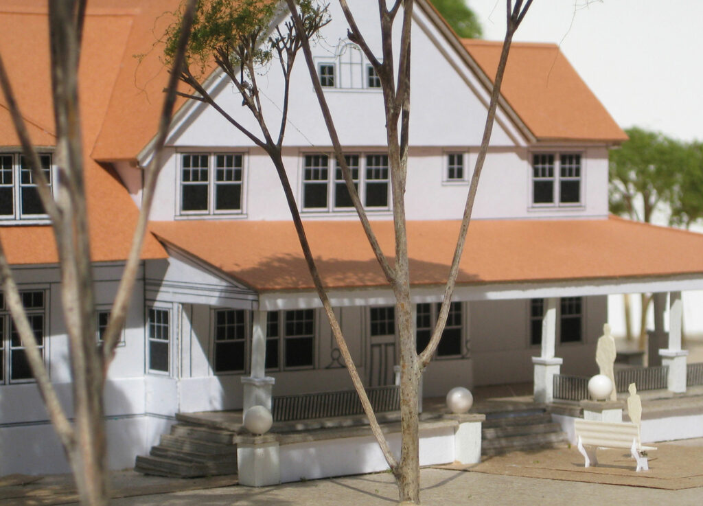
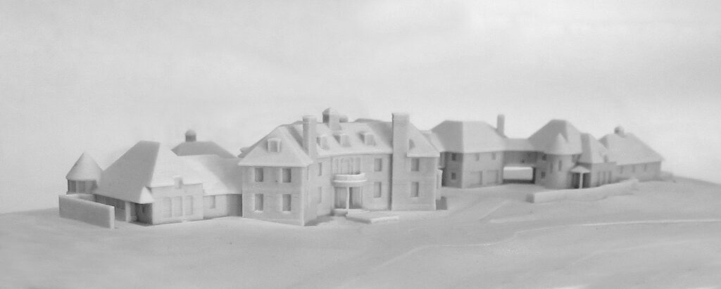
Lastly, traditional PHYSICAL 3-D SMALL SCALE MODELS are sparingly prepared by an architect to represent an architectural concept where digital and graphic 3-D representations are not adequate. Physical, small-scale models of houses are either crafted by hand with traditional model building materials such as balsa wood, chipboard and foam core; or are fabricated using specialty 3D printer equipment.
Using the visual communication tools and practices described above from initial conversation between client, builder and architect through to completion of the construction phase of the projects, we elevate the process of collaboration with our clients, consultants and contractors. We have a powerful arsenal of skills to support the effective communication of the architectural intent as well as continuous refinement throughout the architectural design process. As a result of the successful utilization of these visual communication tools, Archer & Buchanan has—for over a quarter of a century—continued to deliver appropriate and completely unique, winning architectural solutions and services to our clients.
– BACK TO ANNOUNCEMENTS –